Desktop Power Supply from a PC
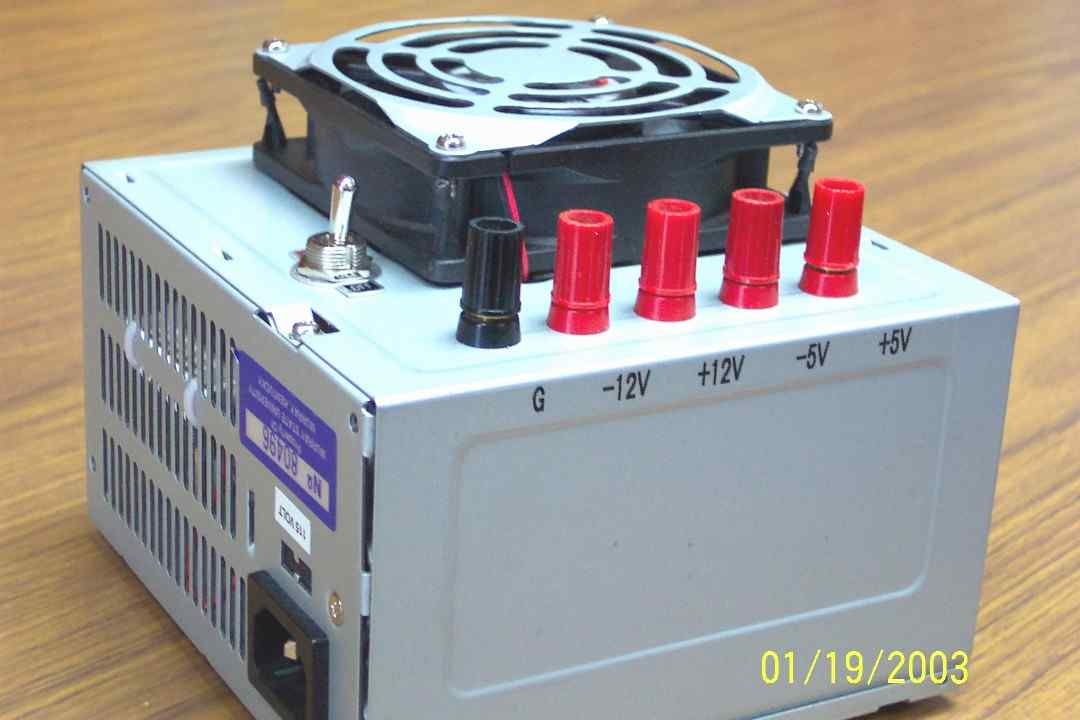
A completed 145 watt ATX power supply with
switch, binding
posts, labels and feet. Notice the zip ties in the ventilation
slots
that
hold the load resistor.
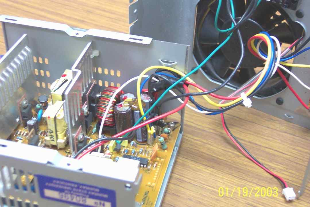
This ATX PS board has leads for +5 (RED), -5 (WHITE),
+12
(YELLOW), -12 (BLUE) volts, Ground (BLACK) and switch (GREEN). Dell
power
supplies manufactured between 1996 and 2000 do not follow the industry
standard
pinout and color codes. The fan has also been unplugged for better
viewing.
Since this PS was converted for use in the logic and robotics labs, the
selected
voltages were tapped. Other users may want combinations of +3.3 V
(ORANGE), +5 V
and/or +12 V if they are converting one of the newer supplies. For R/C
applications, the 5 volt output can also serve as a desktop source to
drive
receivers and servos. If used as a power source for the micro and
sub-micro
servos, you must be careful not to drive the servo to either endpoint to
avoid
stripping the smaller gears in these units. Most standard servos have
sufficiently robust gear trains and will simply stall if pushed to the
mechanical stops..
Measured voltages on this particular PS (1996
P5-100 20
MHz Gateway) were about 5.15 and 11.75 volts. The remaining leads have
been
clipped off at the circuit board.

View of the case top with fan, binding posts and switch. The switch (SPST) and binding posts are available at Radio Shack or other electronics suppliers.
Power supplies in today's computers are
known as
SWITCHMODE or Switching Mode power supplies and require a load to
continue to
operate after being switched on (the term switching mode actually applies to the
technique of A/C to D/C conversion and not to the power up action). This
load is
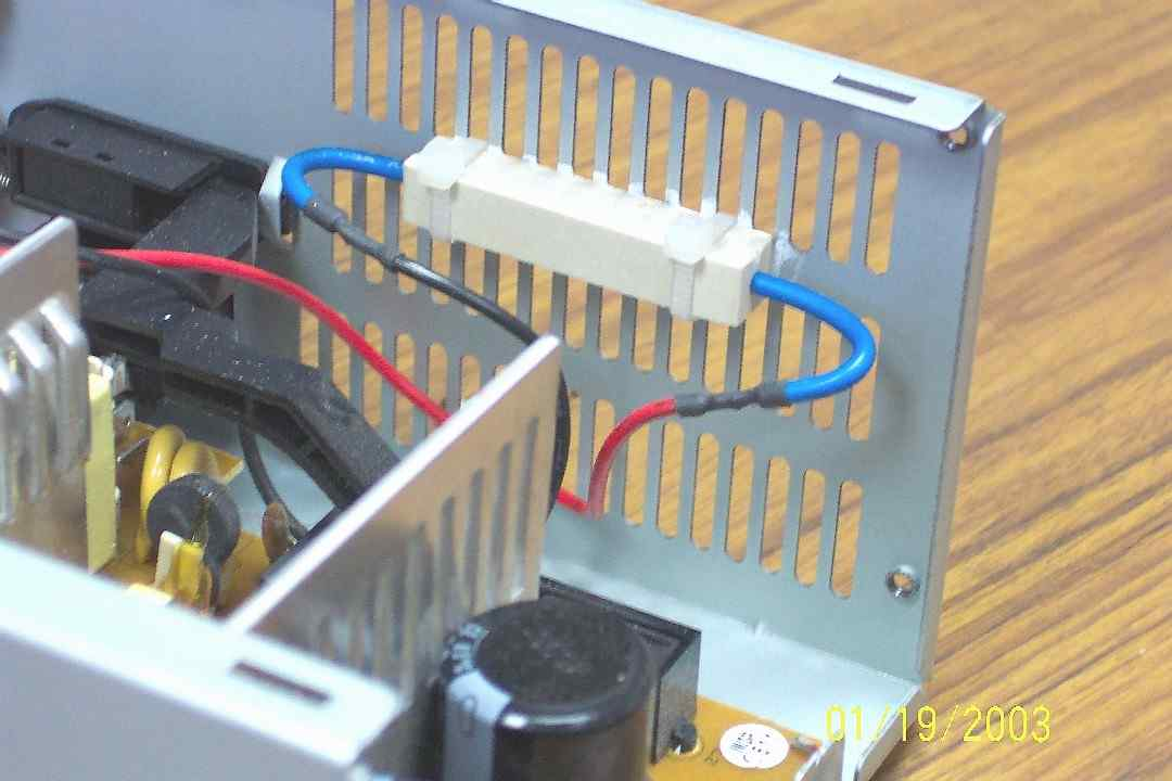
provided by a 10 watt, 10 ohm wire wound load resistor (sandbar about
$0.80 at
Radio Shack) across the +5 volt supply. Some inexpensive power supplies
may fail
if forced on without a load. The sandbar has been zip tied to the case
with a
small amount of heat sink compound applied. Without cooling, the
resistor will
get very hot and may fail prematurely. With this arrangement, the
resistor will
remain barely warm to the touch.
Be warned that many of the heat
sink
greases can be quite toxic and any excess should be cleaned up and
disposed of
properly. Also be sure to thoroughly clean your hands and tools after
use. While
most heatsink compounds are rated to 160 to 170 C, some may dry out over
time
and their effectiveness will diminish -- a periodic check for good
contact
between the case and resistor is a recommended practice.
Additional comments
Disclaimer: The information presented should not be considered a "HOWTO"20
article, but merely a documentation of my conversion process. Modern PC
Power
Supplies can produce high output current levels that may cause internal
overheating in the PS or damage to devices connected to them. Any
individual
attempting their own conversion is cautioned to carefully research their
PS
specifications and to be mindful of the associated voltages and power.
DO NOT
work on your opened power supply with it plugged in!!!!
The
PS in
the picture is a 145 watt ATX salvaged from a 1996 P5-100 MHz Gateway --
I
salvage all usable parts from the older PC's before dumping them. This one is
set up for a logic lab, hence the +5, -5, +12, -12 volt taps. We also
use the +5
to drive servos in the robotics lab. This supply does not have a 3.3 V source,
but the newer supplies do. INTEL has continued to modify the ATX
specifications
to include additional power connectors to support the increased power
requirements of the newer motherboards.
Before any modification
attempted, you should be sure of the type of power supply you are working with
and the output currents being produced at each voltage level. Higher
wattage
supplies can generate fairly hefty levels of current and may overheat or damage devices attached to them. See the
Table of Representative Current Levels for other power supplies
Wiring coming off an industry standard circuit board will be:
| ORANGE
| +3.3 V
|
| YELLOW
| +12 V
|
| BLUE
| -12 V
|
| RED
| +5 V
|
| WHITE
| -5 V (May not be present on recently manufactured supplies)
|
| BLACK
| GND
|
| GREEN
| POWER-ON (Active high -- must be shorted
to
ground to force power up)
|
| GRAY
| POWER-OK What is this??
|
| PURPLE
| +5 V STANDBY
|
| BROWN
| +3.3 V REMOTE SENSING See the
Design Guide Update
|
The yellow, red and black wires will likely be grouped
together
with a clip. Some of the PS's will have a detachable plug for the fan
and some
will have the fan permanently attached to the circuit board. If the fan
is
attached, I usually clip the wires then re-solder and cover with heatshrink
tubing -- this gives more working room while modifying the PS and allows
me to
lube the fan.
If you are going to use only the +12v and +5v, you
may
clip the other wires at the circuit board level or leave the unused wires about
an inch long, gather common colors together, slip a piece of heatshrink
tubing
over the bundle and shrink -- it is an easy way to corral and insulate
loose
ends.
For the +5 / +12 volt PS, you will need the following
combinations:
| GREEN / BLACK
| Power on Switch (Use a SPST
switch; a
momentary switch will not work)
|
| RED / BLACK
| Pre-Load Resistor (See text for recommended =
values=20
and a possible substitution)
|
| YELLOW / BLACK
| +12 volt source
|
| RED / BLACK
| +5 volt source
|
| ORANGE / BROWN
| See the
Design Guide Update
|
I use a single
common post (GND -
black) for all voltage sources. Our loads are light and we don't require
separate grounds for each.
Leave 3 black wires -- switch, load
resistor
and common (GND) binding post
Leave 2 red wires -- 5 volt binding
post
and load resistor
Leave 1 yellow wire -- 12 volt binding
post
Leave the green wire -- power on switch
If sense
wires are
present, refer to the
Design Guide Update
If you expect to place high current demands on your
powersupply, it may be prudent to run two wires to each binding post --
while it
is very unlikely that the 18 AWG wire will overheat, there have been
some
instances of melted wires and connectors occurring on high demand
motherboards.
As an aside, you can get 7 volts from the +5 V and
+12 V
outputs -- the +5 V is considered the negative (GND) and +12 the
positive --
some geeks will use this combination to run their fans at a lower speed
to
reduce noise.
I've followed all the instructions, but the output voltage on the +12
V side
is still low -- what can I do?? Many of the R/C folks are converting
power
supplies for the purpose of driving field chargers and are finding that
voltage
levels below 12 volts are sometimes insufficient to power their
chargers. Read
these TIPS
for some options that may help increase this voltage level, provide a
little
theory, identify the connector pinouts found on most PC supplies and
give a few
troubleshooting hints.
Cut everything else off even with the board. I
usually
cut the power harnesses so I can keep as much together as possible. The
wires
remaining in the power supply should be left long and cut to length as
needed.
If you leave them too long, they will get in the way when boxing it up,
especially if the fan is internal rather than external. Be sure that
they stay
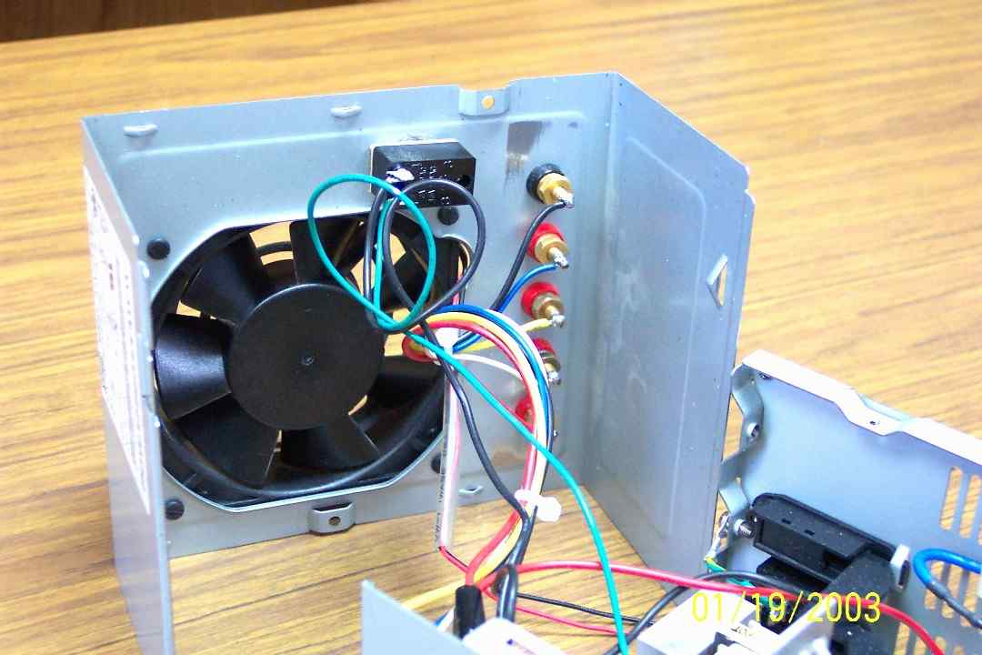
out of the way of the fan blades. Also be sure to reattach the fan -- some
supplies will not function without the fan attached - in any event, you
need the
cooling. This PS in the pictures has the fan mounted on rubber shock
mounts and
is extremely quiet. I will also disassemble the fan and lube the
bearings while
I have the PS open. Since these are salvaged, the fans have been in use
for some
time and normally the bearings are dry -- I use a high grade sewing
machine oil
from SINGER. Any light oil will work, just don't use WD40
--
These power
supplies are called SWITCHMODE or SWITCHING MODE power supplies and must
have a
load to function -- hence the 10 ohm 10 watt load resistor on the 5 volt
line.
These resistors are known as wire wound or sandbar resistors and can be
purchased from Radio Shack for about $0.80 each. This resistor will get
hot and
should have some sort of heat sink. The technique I use keeps them
amazingly
cool and is easy to do -- just pick the flattest side of the resistor,
apply
some heatsink compound (see warning above about toxicity) and attach to
the
case. I will usually hit the inside of the case with a file to remove
any
stamping flash on the ventilation slots. The switch (single pole, single
throw)
and binding posts can also be found at Radio Shack or other electronics
supply
houses.
Resistor Substitute
A viable alternative to using a
power
resistor is to substitute an 1157 automotive signal lamp in its place.
This is a
dual filament lamp and its load, with both filaments powered, is usually
sufficient to maintain Latch_On and to raise the voltage on the 12v rail
to an
appropriate level for most needs. Your options are to solder a 5v line
(red) to
both positive pins on the lamp and ground the base to DC ground or to
pick up a
twist-lock socket when you buy the lamp. The advantage of using a socket is the
ease of replacement should the lamp fail. If you don't feel comfortable
with
your soldering skills, it is also a little easier to work with the
wiring on the
socket rather than the pins on the lamp. Just remember that the socket
housing
is the ground and the two wires in the base are to be attached to the 5v
rail.
More importantly, you must be very careful that neither the bulb base
nor socket
housing touch any of the internal components in the power supply. These
lamps
may be purchased at any automotive supply store and most Walmarts.
I
prefer the use of resistors since the final converted product is wholly
self-contained and I have more control over the applied load, but the
use of a
lamp does simplify finding and installing components. It also makes a very
obvious Power_On indicator!
I usually deal with on-line
suppliers such
as Jameco, Digikey, Mouser, etc. because we are buying in larger
quantities and
Radio Shack is too expensive for large numbers of items. However, you should be
able to convert your PC supply for $5.00 or $6.00 dollars -- less if you
have a
junk box of parts. I suppose you could add an LED indicator with a 220
ohm
dropping resistor to the 5v rail to show the PS is turned on, but the
fan is a
pretty good hint. We have had supplies running 24/7 for months without
problems
-- just electricity consumption.
The PS has some fairly hefty
electrolytic capacitors and can still give a bit of a shock immediately
after
being unplugged -- let it sit a couple of minutes before poking around
inside.
Obviously, you can get whacked if you are inside the case with it still
plugged
in -- probably won't kill you, but you WILL turn it loose (never mind
how I
discovered this bit of information).
If you have any questions, comments or corrections, feel free to mail me.